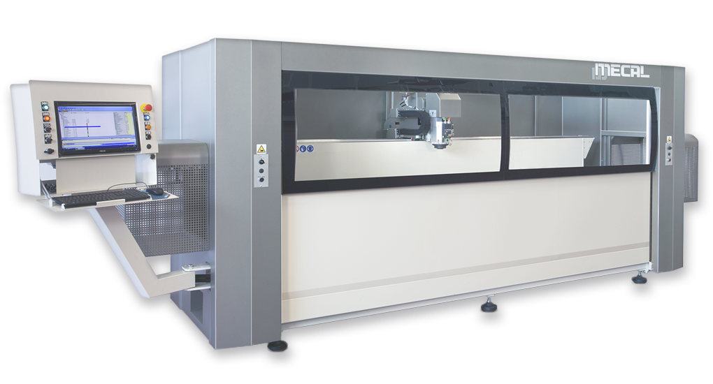
MC 309 NIKE MU DPM

MC 309 NIKE MU DPM

3 axis CNC + 1 axes pneumatically managed floor-type vertical-spindle machining centre.
  • DPM = version provided with a device activated by a pneumatic/electronic combination dedicated to the automatic movement of the single clamps.
  • 3 axis (X, Y, Z) controlled by CNC + 1 axes pneumatically managed.
  • Suitable for the machining of aluminum profiles for the sector of windows and door.
  • The positions 0° and ± 90° of the rocking beam are fixed; intermediate angles are manually settable and managed with a pneumatic system through the software.
  • The workpieces are fixed with 4 pneumatic clamps, sliding on the tilting beam. The beam can be positioned at any preselected angle within ± 90°, managed directly by the CNC control.
  • Workable section: 200 x 170 mm (YxZ).
  • View Technical Data
    X-axis strokemm3500
    Positioning speed X-axismmm/1’70
    Y-axis strokemm370
    Positioning speed Y-axism/1’30
    Z-axis strokemm348
    Positioning speed Z-axism/1’30
    A axis strokedeg± 90°
    Electrospindle rated powerkW3,8
    Cooling systemAir
    Tool holder coneISO30
    Max rotation speedrpm18000
    Weightkg± 2200
    Subject to technical changes
Download the PDF with the useful areas

Features

Features - MC 309 NIKE MU DPM

  • Electro-welded sheet base which has been designed in such a way to offer the maximum rigidity and use practicality.
  • The axis slide on precision profile guides and are driven by motors operated with digital systems.
  • Profile holder system (no. 4 clamps) slides on precision guides.
  • The locking clamps slide on precision guides and can be positioned automatically by the mobile upright.
  • The positioning of the clamps beam at intermediate angles is done with the manual positioning of mechanical devices dedicated. These devices are managed automatically by the duty cycle so as not to be prevented when they are not mentioned in the work program.
  • 5-position tool magazine on the machine. It may contain tools for drilling, milling, tapping, end-milling. A second magazine can be added on the right side.
  • Linear and circular interpolation on the axis X-Y-Z.
  • By using the disc cutter it is possible to carry out end-milling on both ends of the workpiece (end-milling cycle).
  • By means of dedicated tools it is suitable for working on 5 sides of Aluminium, PVC and steel sections.
  • The 2 hinging length stops are pneumatically operated.
  • The electric-spindle is suitable for quick tools change.
  • The tools cooling is done through a centralized system that optimizes the required minimal lubrication.
  • The useful stroke for working bars is 3270 mm with blades Ø 150-200 mm; for longer pieces, the differentiated machining cycle can be used, up to the double of the useful stroke (6540 mm).

Equipment

Equipment - MC 309 NIKE MU DPM

  • No. 1 electric spindle air cooled, ISO30, rpm 18000, kW 3,8
  • No. 1 tools magazine (5 seats)
  • No. 4 clamps system
  • No. 2 hinging length stops, pneumatically managed
  • Group for the treatment of compressed air (filter / Lubricator / Regulator)
  • PC desktop
  • Display TFT-LCD 18,5” W, keyboard QWERTY, mouse
  • Operative system Windows
  • License MS WINDOWS
  • CAD CAM 3D Graphic software

HARDWARE & SOFTWARE

CAD CAM 3D - The new MECAL 3D software for the management and programming process of machines. - MC 309 NIKE MU DPM

Easy of use
  • Developed to render the approach for programming the machine tools to be the most intuitive possible, without the need to specifically know ISO language.
  • It is characterized by a human machine interface, a machine purposely studied to render the usage of software and the development of all the necessary operations in the simplest possible way.
  • All of the basic programming is already inserted as a macro, and can be applied to the various sides of the part even by means of the drag & drop function.
Advantages
  • The representation of the work piece in 3D, how to lodge it inside the machine and of the tools to be used allows to avoid errors and reduce the chances of damaging the machine.
  • At the beginning of the process, a completion time will be provided; this facilitates the planning for production.
  • CAD CAM 3D is compatible with main calculation and construction software programs, like Wictop, Logikal, Klaes, Schücal, Opera, … (to mention the most well known).
  • It permits easy uploads of these programs, and programming of the machine with the aid of a barcode reader.
Simulator
  • With CAD CAM 3D it is also possible to purchase a simulator, that allows for verification of timing and production of work process without the need to actually test parts on the machine.
Automatization of production
  • The converter IGES imports external designs completed in SW CAD 3D and creates in automatic the program to process the work.
  • This characteristic is in high demand in the industry sector where the designs are often submitted in CAD like Inventor, Solid Works, Solid Edge, etc.
  • With this software the work process of the machine limits the positioning of the clamped part and the selection of the work to be processed; this will be recognized by the automatic program.
  • In this phase, modifications pertaining to dimensions and type of work process can still be made, while some other selections can be excluded.
SVG cover layer an animated layer to switch from one slide to the next one

MENU